Honda Xr200 Wiring Diagram, Skygo150 Voltage Regulator for XR200/Actual Wiring/Honda XR200 Modified/Supermoto/DIY Garage PH, 10.03 MB, 07:18, 10,383, D I Y Garage PH, 2021-01-23T08:48:03.000000Z, 19, Iam looking for a 1982 honda xr200 wiring diagram, www.justanswer.com, 904 x 703, jpeg, wiring diagram 1982 honda xr200 xt200 yamaha manual iam motorcycle looking 1981 mechanic bikee wire, 20, honda-xr200-wiring-diagram, Anime Arts
We deliver intermittent ignition controls to hvac professionals and homeowners in the usa and internationally. The su instructions show 25v (2) twice (both in the switched and unswitched leg of the transformer) and indicate that the 24v terminal is unused, which was the source of my. Visit our stores or shop online at airhvacrefrigeration. com and get free shipping. • provides ignition sequence, flame monitoring and safety shutoff for intermittent pilot central furnaces and heating appliances.
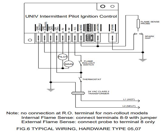
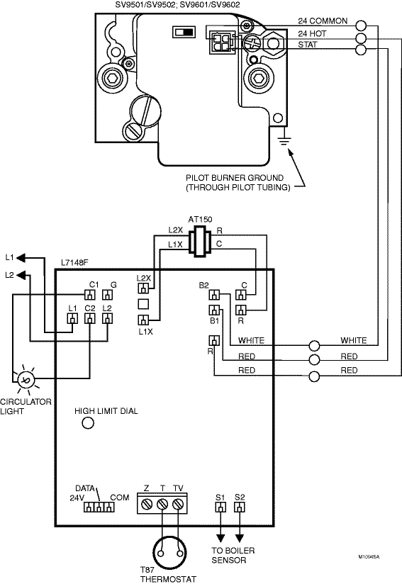
The intermittent pilot ignition control is short cycling. I ordered a replacement one. However, with everything else now days, the newer one does not match the older one. 8 g67 intermittent pilot ignition controls technical bulletin y75 flame sensor thermostat power supply 24 vac 1 2 4 3 high voltage cable high limits in this line only jumper pilot burner ground ground terminals mv pv 5 power is wired directly to r (common) on the thermostat. Terminals 1 and 2 on the g67 are tied together internally. Wiring diagram for g67b( ) Universal intermittent pilot ignition module replaces multiple field installed intermittent pilot modules supplied by honeywell, robertshaw, johnson, and utec (hsc). It uses existing intermittent pilot burner and includes cross reference, instructions, and accessories for easy replacement. Almost always, the wiring diagram is included in.
Honeywell S8610u In Place Of Honeywell S8600m Wiring Diagram

Standing Pilot Wiring Diagram - Complete Wiring Schemas

Honeywell Ignition Module Wiring Diagram - Wiring Diagram Schemas

Honeywell S8610u Wiring Diagram - Diagram Resource Gallery

Honeywell Ignition Module Wiring Diagram - Wiring Diagram Schemas

Honeywell S8610U Wiring Diagram / Honeywell S861ou 1009 Universal Intermittent Pilot Ignition

Step 8. wiring the fireplace, Warning, For intermittent pilot ignition wiring | Hearth and Home
Figure 10. standing pilot ignition wiring diagram | Hearth and Home Technologies SMART-STAT-II
More information on How Intermittent pilot Systems began (5059 Control Discussion) — Heating

Dakota Supply Group | Intermittent Hot Surface Pilot SmartValve®. Standard Opening. 1/2 x 1/2
